- Intel® Core i5 or better
- Windows® 11
- 4 GB RAM (depending on the OS)
- 16 GB free space on the hard drive
- Screen resolution of 1440 x 900 or higher
- Connection to the Internet
- Bluetooth (SPP)
- USB port
- Adobe Acrobat Reader 8.0 or higher
- Recommendation to turn off sleep mode
NOTE Windows® support on the Windows® 10 operating system will end on 14 October 2025. This means that we can no longer guarantee that our CARS and TRUCKS software will work optimally on computers still using Windows® 10.
Please follow the recommendations above
In order to install the software you need to use the USB safety dongle connected to the ICON. It is located in a socket at one of the short ends of the unit. The dongle is programmed to work only with the specific serial number of the ICON that it was delivered with it.
The dongle is a security dongle that not only protects the software from unauthorised access, it is also the device connecting the ICON to the correct software license level.
Here is how you install the Autocom software:
- Insert the USB security dongle into the USB port of the computer.
- Follow the instructions in the installation wizard.
- The License Activation Tool (LAT) will start automatically and connect to the Internet to retrieve accurate license information for the unique VCI serial number. The installation will now start and the dongle will control what installations are available.
Download release
Please note that it is also possible to download the full installation package from https://autocom.se/en/releases.
Follow the instructions to complete the download and installation.
NB!
Antivirus programs and other similar programs may sometimes cause problems with the automatic
start-up of the Autocom software. If the start-up does not work or if it takes long time, please de-activate the antivirus programs. Examples of programs known to cause problems are McAfee VirusScan and ZoneAlarm. Once the installation of the Autocom software is done, the antivirus programs can be re-activated.
Bluetooth
Make sure the Bluetooth is active on the computer, that the VCI is powered via the OBD-socket and within range.(Maximum range is 10 open meters.)
- Go to Settings and Hardware setup.
- Under Bluetooth Hardware you press Search.
- Select the right HW.
- Press Test and confirm with OK.
- If the firmware needs to be updated, you will be informed about this and you will be needed to do that update as well.
USB
Autocom CARS and TRUCKS contains large amounts of sensitive vehicle data. This data needs to be protected from unauthorised access. That’s why a login is required for the software.
Before you login for the first time
In addition to a computer with a valid CARS and/or TRUCKS software licence, you will also need a mobile phone and an email address linked to a Autocom Secure Gateway account.
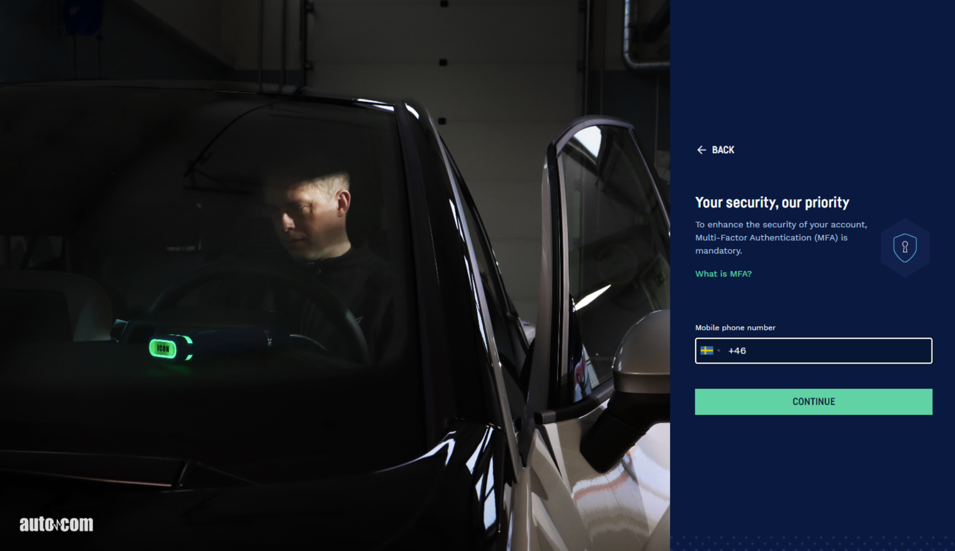
The first time you log in, the process takes place in two steps. The first step involves signing in with your email address and password. The second step is a multi-factor authentication (MFA), where you need to enter a few codes to proceed.
Once you have completed the full login process, you will not need to repeat the MFA steps as long as you continue using the same diagnostic software on the same computer.
How long does the login last?
You will not need to log in every time. As long as you use the software continuously after your initial login, you won’t be asked to log in again. However, to access systems protected by the Secure Gateway, you will always need to log in.
Do you have to log in every time?
You can access the software without logging in. However, if you choose not to log in, you won’t be able to access the Secure Gateway or the OE data stored in the database. If you initially choose not to log in, you can still do so later whenever you need to access a system that is protected by the Secure Gateway.
If you use both CARS and TRUCKS, you will also need to log in when switching between the software applications.
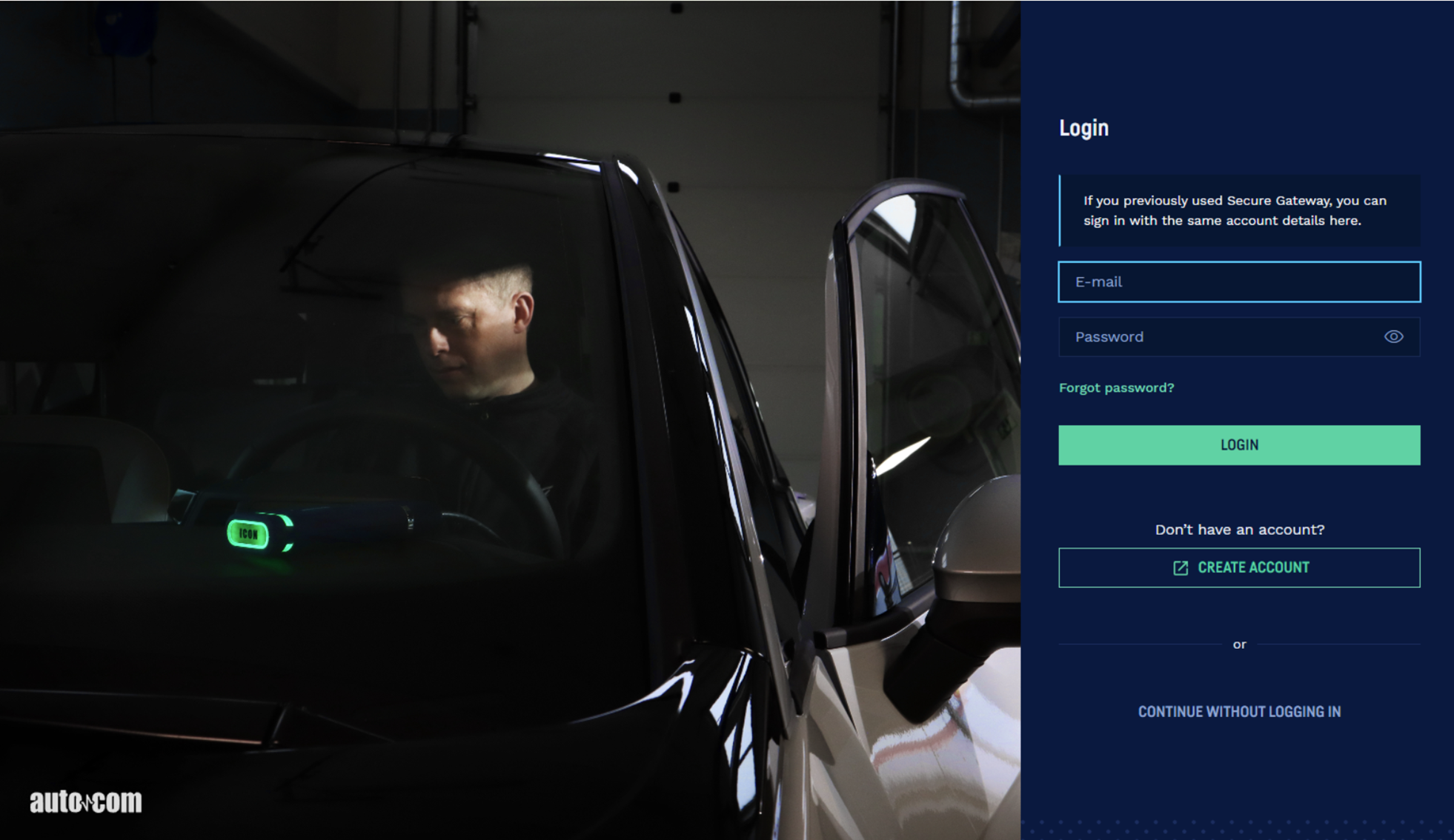
Step-by-step guide
- Start CARS or TRUCKS.
- Log in with your Secure Gateway account. If you don’t already have an account, click CREATE ACCOUNT to create one.
- Enter a mobile phone number. (You will receive a verification code via SMS to that number.)
- Click CONTINUE.
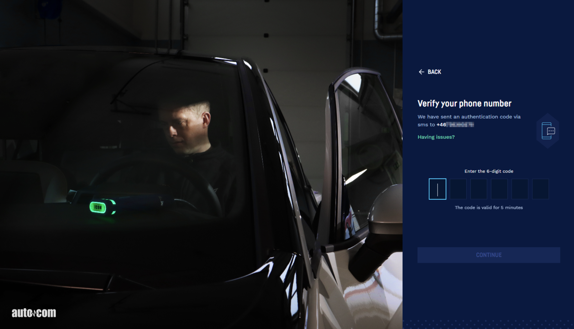
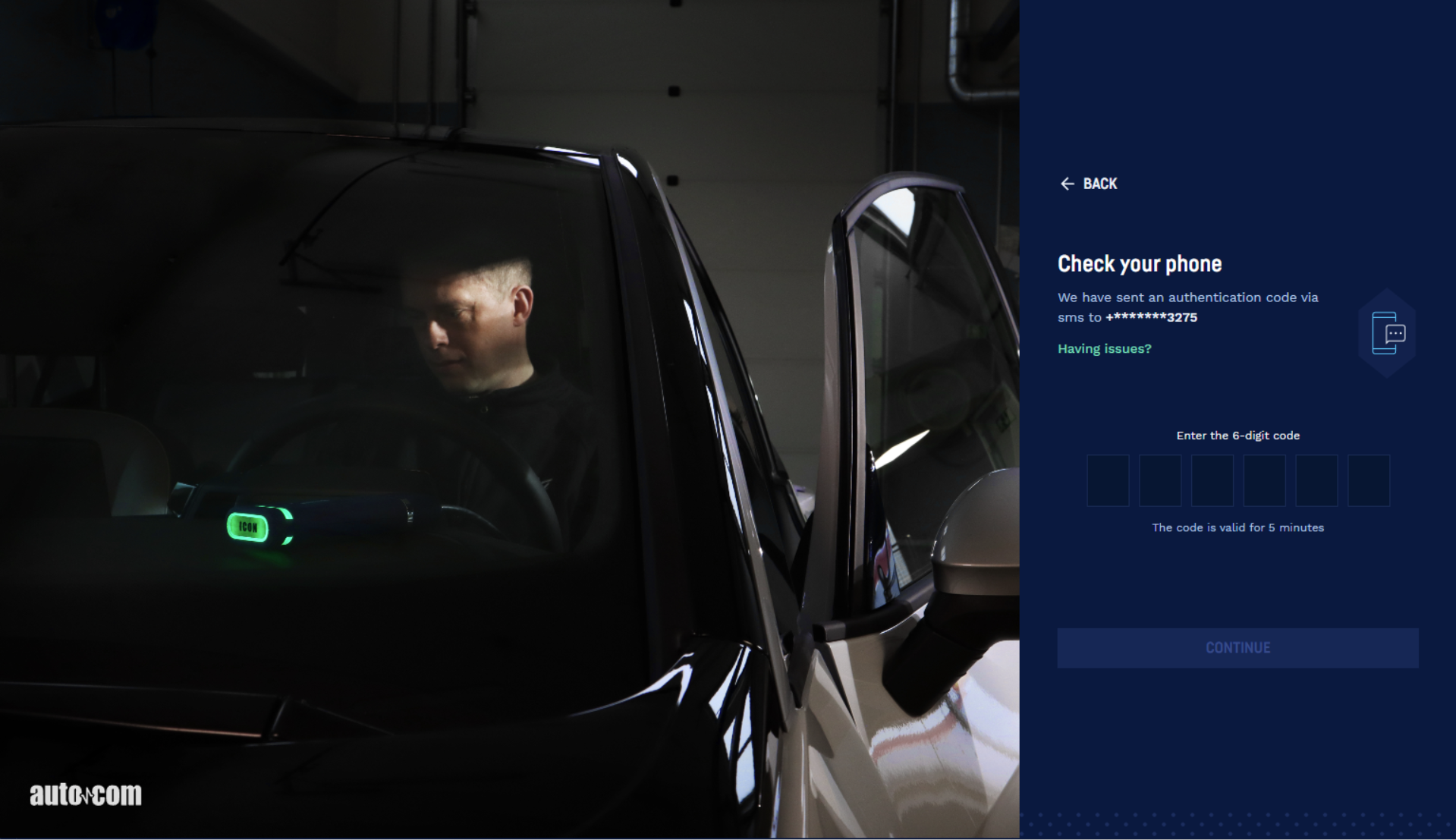
- You will now receive a verification code via SMS to the mobile number you just entered. The code is valid for a few minutes.
- Enter the code in the diagnostic software.
- Click CONTINUE
- Choose whether you want to trust the device — meaning you allow this computer to be used again for your next login without repeating the full process.
If you choose to trust the device (i.e. click TRUST), you won’t need to repeat steps 2–8 as long as you continue using the same computer. By trusting the device, you will also gain direct access to the Secure Gateway.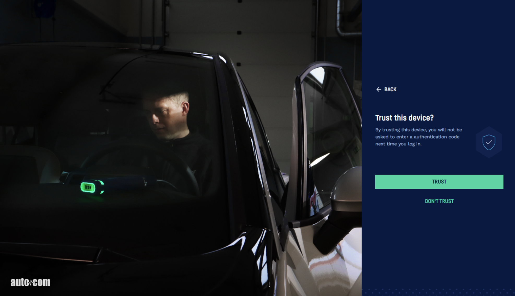
You will now have access to the diagnostic software.
The steps 9-10 below only need to be completed the first time, provided you are using the same computer. - You will receive another code via SMS.
- Enter the code and click CONTINUE.
You have now completed the login in and can carry on reading about important information and about the functions in the diagnostic software.
Software and data are the property of the supplier, and are protected against unauthorised copying by copyright legislation, international contract regulations, and other national rules.
Copying or sales of data, or software or parts thereof, is punishable by law. In case of any violation, the supplier reserves the right to prosecute and demand compensation for damages.

CAUTION
This equipment is not suitable for use in locations where children are likely to be present.
Risk of fire or explosion if the battery is replaced by an incorrect type. (See battery replacement instructions in the manual)
The software CARS and TRUCKS is entirely developed and programmed by Autocom in Trollhättan, Sweden.
We always do the utmost to optimise our products to suit the markets and regions where the products are sold and used.
As a step in this process, we have automated the setup of geographical preferences during the installation. The only choice the person installing the software has to do is to choose the applicable country.
By making a correct choice of country during the installation of the software, the customer is ensured to have the best setup to fit regional conditions regarding content of the vehicle database as well as the functionality of the program. The applicable vehicle population and local conditions will then be maximised.
OBDII cable torch battery replacement
Battery replacement safeguards for the 2 x CR1216 batteries in the cables.
- Make sure the OBDII connector is disconnected from any power source (e.g. vehicle or power
adapter). - Make sure the USB-C cable is disconnected from any power source (e.g. computer/tablet/cell
phone or power adapter). - Use a torx 10 screwdriver and remove the 2 screws on the back side of the OBDII connector.
(See Picture 1). A small screwdriver might be necessary to pry out the screws. - Use a small Philips screwdriver to remove the 4 screws of the battery fastening plate. (See
Picture 2) - Remove the battery fastening plate. A small screwdriver might be necessary to pry off the
plate. (See Picture 3) - Remove the 2 x Renata CR1216 3V Lithium button cell batteries. Note that the + poles are
facing upwards. (See Picture 3) - Replace them with new 2 x Renata CR1216 3V Lithium button cell batteries. Make sure that
the + poles are facing upwards. - Repeat step 3 to 5 in reverse.
Picture 1 below
Picture 2 below
Picture 3 below
To the greatest possible extent, all data in the softwares are based on information from vehicle manufacturers. The supplier does not guarantee that data or software is correct or complete. The supplier does not accept liability for damages caused by defective software or incorrect data. In all cases liability is limited to the amount that the buyer has paid for the product at the time of purchase. This exemption from liability does not include damages caused intentionally or by gross neglect on the part of the customer.
All use of hardware and/or software that has not been approved by the supplier is seen as a modification of our products, and thus there are no valid warranties.
Our products may not be modified in any way. Only genuine accessories and spare parts may be used, which also applies to adapter cables. All breaches of this will void any claims.
The diagnostic equipment may only be used with operative systems approved by the supplier. If the diagnostic equipment is used with an operative system that is not approved by the supplier, the warranty cease to be valid. Also, the supplier does not accept any liability or responsibility for damages and consequences thereof that have arisen due to the use of a non-approved operative system.
Note that the vehicle manufacturer’s instructions must be followed when working on a vehicle. The supplier does not accept any liability or responsibility for damages and consequences thereof that have arisen due to not following the vehicle manufacturer’s instructions for the vehicle.

This label shows that the product is manufactured after August 13, 2005, and therefore it shall be recycled according to WEEE (EU Directive 2002/96/EC regarding waste from Electrical and Electronic equipment). Contact your local distributor for more information.

There are a number of options to select and identify your vehicle.
1. AutoVIN (Automatic Vehicle Identification Number)*
The fastest and easiest way is to make the VIN decoding fully automatic;
– Go to “Settings”
– Activate “AutoVIN”.
From now on the VIN will be automatically read out when connected to a vehicle.
*Only for ICON
2. VIN (Vehicle Identification Number)
By using the VIN decoder, you enter the vehicle VIN and you will then be directed to the correct brand, model and year model selection.
3. eOBD standard protocol
There is also a possibility to readout the VIN from the vehicle using eOBD standard protocol. Simply press the magnifier icon within the VIN field.
4. VRM (Vehicle Registration Mark)
For some regions there is also a possibility to enter the VRM to select brand, model and year model

Read out fault codes from the vehicle’s control system.

Erase fault codes will delete saved malfunction information from the control system’s memory.

Shows input and output signals, values and program information from the system.

”Component Activation” is a way for the diagnostic system to force the control system to bypass its own control function and to let the diagnostic system control/change the output signal.

An advanced function where the diagnostic system is used to change the control system’s functionality, temporarily turn off functions in the control system or control system functions in the control system.
Before an adjustment function is performed it is important to read through the help instructions and to follow the instructions in the diagnostic system. Not following instructions and directions from the diagnostic system means risk of damaging the vehicle’s control system.

The function ”Write to ECU”, also called “coding”, is an advanced function where the diagnostic system is used to add new information to the control system.
Examples of coding functions are injector coding, key coding or replacement of a complete control system/actuator. Before a coding function is performed it is important to read through the help instructions and to follow the instructions in the diagnostic system.
Not following instructions and directions from the diagnostic system means risk of damaging the vehicle’s control system.
Will show at the bottom center of the screen when brand, model and year model have been selected.
The function scan through the control systems that are chosen/marked in the list. The software reads out fault codes stored in the control systems. The result is presented for the chosen control systems.
- Green – the control system answers correctly and there are no fault codes stored.
- Red – the control system answers correctly with fault codes stored in the system.
- Orange – it is not possible to identify the control system in a single-valued way.
- The user must make a choice.
- Grey – the control system does not answer.
To see the stored fault codes, click on the arrow for each respective system. It is possible to erase fault codes by clicking on the symbol for erasing fault codes in the right corner at the bottom. It is also possible to go straight to complete OBD.
Glossary
Permanent: The fault code is irreversible and present
Intermittent: The fault is periodically recurring, i.e it comes and goes
OBD: On Board Diagnostics
MIL: Malfunction Indicator Lamp
DTC: Diagnostic Trouble Code. Same as fault code
RTD: Real Time Data
ACT: Activation
ADJ: Adjustment
COD: Coding
ECU: Electronic Control Unit. Same as control system, controller, actuator
SAE: Society of Automotive Engineers
ISO: International Organization for Standardization

System Identification identifies and selects automatically the type of controller that is mounted in the vehicle. This ensures that the diagnostic session is performed correctly with the correct parameters as required.

To be able to give the customer a report of what was found and done to the car, it is possible to generate test reports in the software.
These test reports can either be printed out immediately when you have done the test, or saved for future use. If you choose to save a test report, a PDF file is generated.
To save or print a test report you press the button “Print/Save”.
It is also possible to print the help instructions available for certain diagnostic functions.

A function that test a specific system and where components chosen by the control unit is loaded (activated).
A fault code will be saved if the control unit discover any invalid value on the component.
The function ends by automatically reading all the identified fault codes. Follow the instructions before you conduct a self test.

A help text is a guide for an specific part and/or gives you important information of a certain function in the program.
E.g. what does this function do, what kind of information do you need or what kind of information are you expected to fill in.
Use the help button to access help file in the software.

Guided Diagnostics is a great complement to the Autocom software.
The target-oriented information is very valuable for the workshop since you not only get probable causes to a fault code, but also datalists with reference values for parameters related to the fault code. There are also some collected tips and tricks due to the fault code. Based on real problems and solutions.

The Flight Recorder function gives the possibility to record information from a system while driving the vehicle.You can then play back the recording in the program to see any errors that occurred during the test run.
Create a Flight Recorder template
To start a flight recording, the template must be created and downloaded to the VCI.
- Go to the custom datalist under Real Time Data.
- Select one or more parametres. This will enable the Flight Recorder button.
- You can now download the template to the VCI.
Triggers can be set during flight recording. Simply press “REC” and the chosen trigger points will be shown as lines in the graphs after the recording.
Upload a Flight Recorder session
To upload of the Flight Recorder session you
- Press the button and a information window with a short guide will open.
- Upload the session stored in the VCI.
- In the upload window you have a possibility to open a previous Flight Recorder session. When you click the “Open file” button you can browse to find the file you want to display.
- The “Read Template” button connects to the VCI and reads the information. If a session is stored the “Upload session” button is enabled and it is possible to upload the stored data.
- Press “Close” to cancel the action.
Display the Flight Recorder session
When the Flight Recoder session is uploaded a graph window will open.
- In “Combined view” selected parameters are displayed in the same graph window.
- In “Split view” all parameters are displayed in separate graph windows.
- “Scale” is showing the actual value.
The graph window can be zoomed by using the scroll wheel on the mouse. It is also possible to adjust the areas of the window by moving the line between the graph window and parameters list.
Exit the Flight Recorder function by clicking the “Back” button in menu 1.